How Fused Deposition Modeling Works
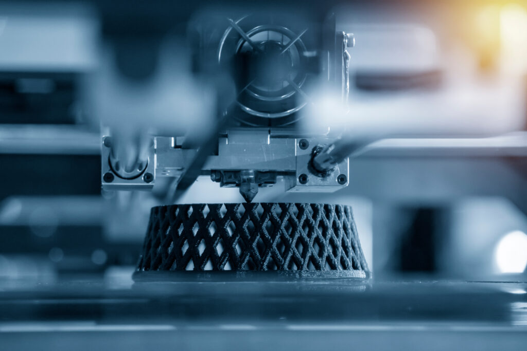
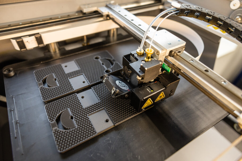
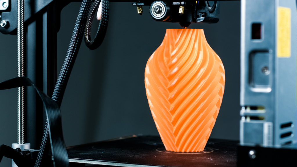
Fused Deposition Modeling (FDM®)* creates more durable parts for tough industrial environments by building each part in successive layers of materials, such as thermoplastic polymers, directly from a CAD file. The process begins with heated plastic filament which is then pushed through an extruder, allowing it to be deposited and solidified into the desired shape. Markforged® reinforces the FDM process through Continuous Fiber Fabrication (CFF), which increases the strength of parts so they’re as strong as aluminum in 2 axes. This process is a more cost-effective, precise solution for detailed prototyping and manufacturing applications.
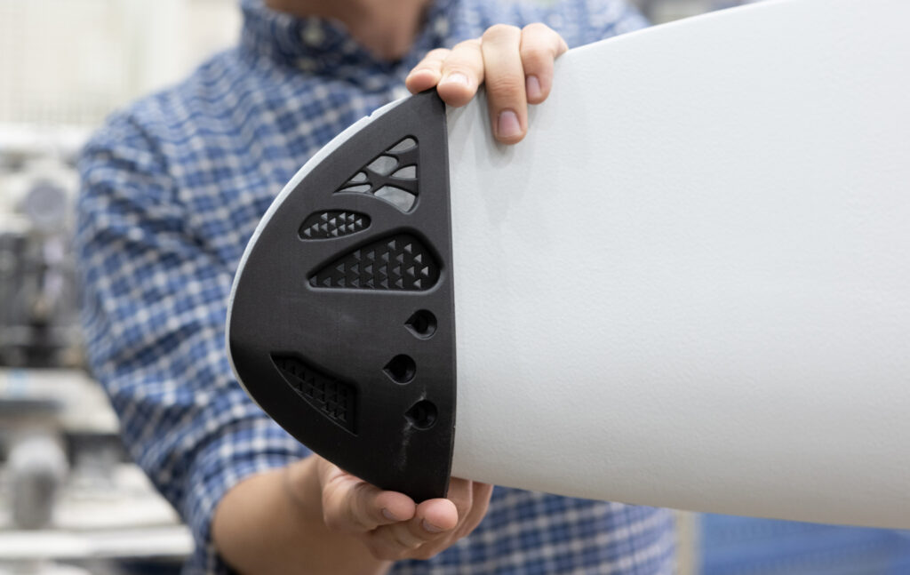
Here’s how our FDM solutions can help you:
- Achieve a low cost-to-size ratio thanks to the scalability of our FDM printers for specific industry requirements.
- Explore more part size options and choices of materials, including a variety of polymers, composites and metals.
- Produce complex parts quickly with high-precision for intricate shapes and a variety of rapid prototyping needs.
- Ensure high performance with engineering-grade materials for automotive, medical, and aerospace manufacturing.
Our Fused Deposition Modeling Capabilities
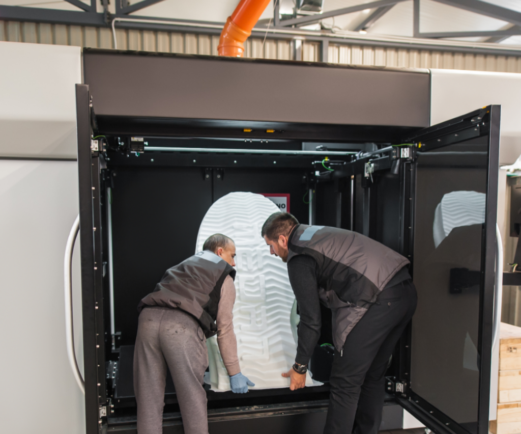
Our team of experts can help guide you through the fused deposition modeling process. Our industry-leading portfolio of 3D printers can produce parts with larger build envelopes to accommodate different size requirements for various industries. Also, our FDM printing technology can be programmed to produce multiple parts simultaneously, allowing prototyping and large-scale production in a relatively short period of time. The material properties of the parts created with this process are also highly reliable.
Dual Build Zones
Markforged Parts
Superior Control
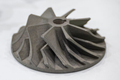
Better Material Options
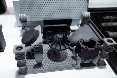
More Applications
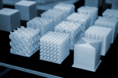
Guiding You to Best-Fit Solutions with Markforged Technology
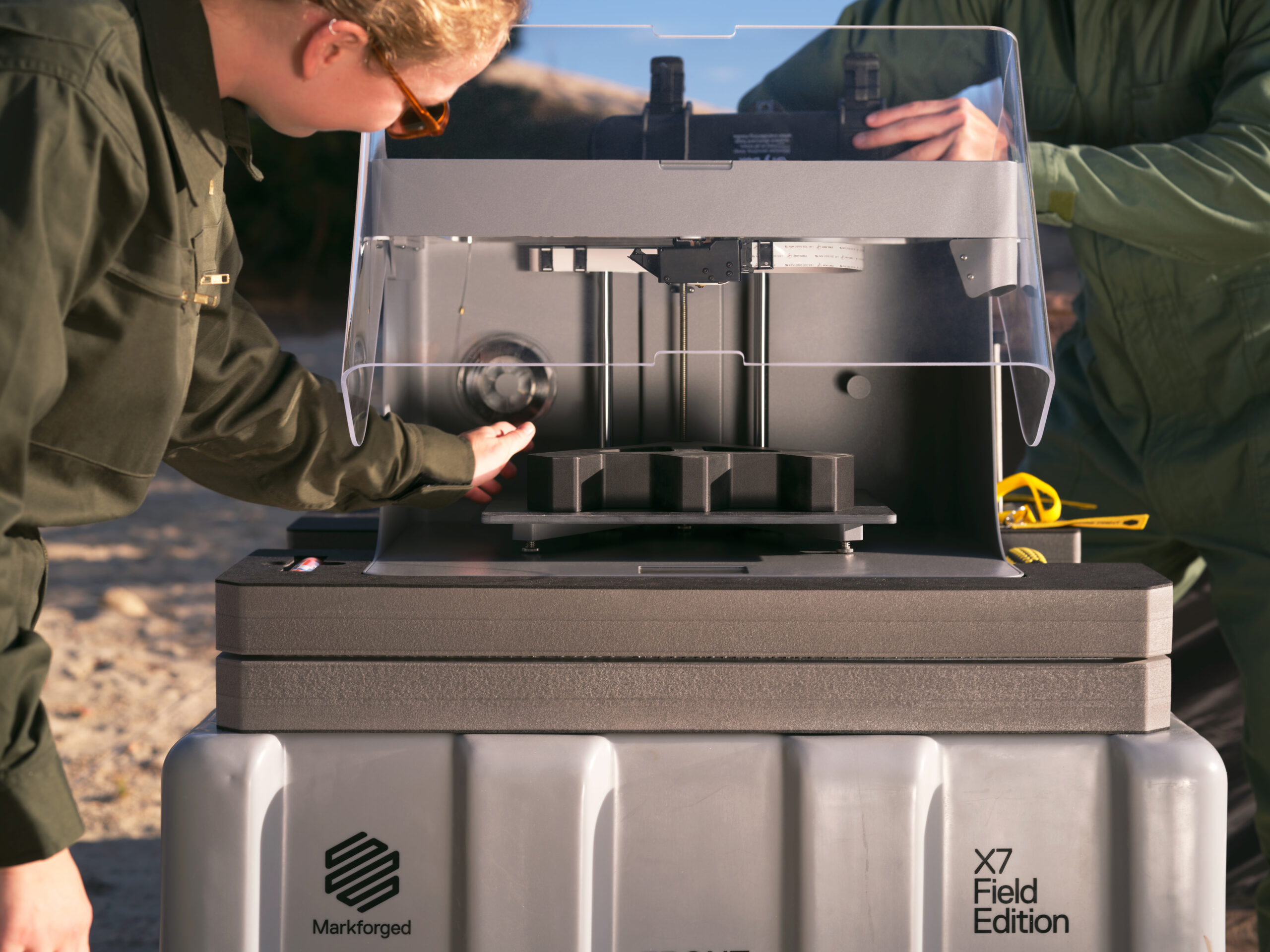
The Markforged X7 printer can weave fiberglass in one piece to make it as strong as metal. The Mark Two combines continuous carbon fiber reinforcement with workhorse reliability for the strongest, most versatile parts. The Metal X safely prints metal powder bound in a plastic matrix with new features such as close-cell infill for reduced part weight and cost — and it’s significantly less expensive than alternative 3D printing and traditional machining/casting methods.
FDM Materials Comparison
| Material | Process | Description | Ideal for | Finishes | Spec Sheet |
|---|---|---|---|---|---|
| A2 Tool Steel | MarkForged Metal X Binder Jetting DED PBF | Excellent toughness, wear resistance, and machinability | Blanking dies, forming dies, and gauges | Machining Heat Treatment, Polishing, Surface Coating, Shot Peening | Spec Sheet |
| ASA | FDM | Weather-resistant material that has good impact resistance and dimensional stability | Automotive components, outdoor equipment, and other components | Painting, Hydrographics, Vacuum Metalizing | Spec Sheet |
| D2 Tools Steel | MarkForged Metal X Binder Jetting DED PBF | High-carbon, high-chromium tool steel that is known for its excellent wear resistance and toughness | Cutting tools, forming dies, and blanking dies | Machining Heat Treatment, Polishing, Surface Coating, Shot Peening | Spec Sheet |
| H13 Tool Steel | MarkForged Metal X Binder Jetting DED PBF | Excellent toughness, thermal conductivity, and resistance to thermal fatigue | Die casting dies, forging dies, and extrusion dies | Machining Heat Treatment, Polishing, Surface Coating, Shot Peening | Spec Sheet |
| Nylon-12 Chopped Carbon-filled | FDM | Nylon material that is reinforced with chopped carbon fiber for improved stiffness and strength | Gears, bearings, and other components | Painting, Coating, Laser Etching, Hydrographics, Anodizing | Spec Sheet |
| Onyx | MarkForged | Carbon fiber-filled nylon material that is strong and stiff, with good dimensional stability and heat resistance | Tooling fixtures, jigs, and other components | Vapor Smoothing Inserts | Spec Sheet |
| Onyx FR | MarkForged | Flame-retardant version of Onyx that is suitable for applications where fire safety is a concern | Electrical enclosures, automotive components, and other applications | Vapor Smoothing Inserts | Spec Sheet |
| PC (Polycarbonate) | FDM | Strong and transparent material that has good impact resistance and heat resistance | Lenses, lighting fixtures, and other components | Painting, Coating, Vacuum Metalizing, Laser Etching | Spec Sheet |
| PC/ABS | FDM | Blend of polycarbonate and ABS materials that combines the toughness of ABS with the heat resistance of PC | Automotive components, housings, and other components | Painting, Coating, Vacuum Metalizing, Laser Etching | Spec Sheet |
| PETG | FDM | Clear and impact-resistant material that has good chemical resistance and dimensional stability | Display cases, signage, and other components | Polishing, Coating, Laser Cutting/Engraving, Vacuum Forming | Spec Sheet |
| Stainless Steel (17-4PH) | MarkForged Metal X SLM EBM | Commonly used additive steel option with excellent strength and corrosion resistance | Aerospace for structural components, medical for surgical instruments and implants, and defense armor components | Electroplating Passivation, Polishing, Powder Coating, Machining | Spec Sheet |
| Ultem 1010 | FDM MarkForged FX20 | High-performance material that is known for its excellent heat resistance, strength, and stiffness | Aerospace components, automotive components, and other applications | Sanding, Machining, Coating, Polishing, Painting, Laser Marking | Spec Sheet |
| Ultem 9085 | FDM | High-performance material that is known for its excellent heat resistance, strength, and stiffness, with the added benefit of being FAA-approved for aerospace applications | Aerospace components, automotive components, and other applications | Sanding, Machining, Coating, Polishing, Painting, Laser Marking | Spec Sheet |
This is a sampling of FDM and MarkForged materials we work with. See more information on available materials and specs here.
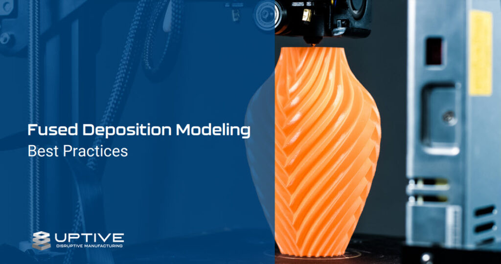
Fused Deposition Modeling (FDM) Design Guide
Fused Deposition Modeling (FDM®)* creates more durable parts for tough industrial environments by building each part in successive layers of materials, such as thermoplastic polymers, directly from a CAD file. Download this design guide to learn more about best practices for using Fused Deposition Modeling.
Why Customers Choose UPTIVE
Latest Insights
Plastic CNC Machining

What is Sheet Metal Fabrication?
Embracing Earth Day Every Day: The Environmental Benefits of Domestic Manufacturing
*FDM® is a registered trademark of Stratasys Ltd.
